You upload a sketch, the ESP32 starts, and then the serial monitor fills up with this, over and over:
1Brownout detector was triggered2 3ets Jun 8 2016 00:22:574rst:0xc (SW_CPU_RESET),boot:0x13 (SPI_FAST_FLASH_BOOT)What is actually happening
The ESP32 has a hardware brownout detector watching its supply rail. When that rail sags below roughly 2.5 V, the detector forces a reset rather than letting the chip run on a voltage where flash writes corrupt and register reads return nonsense.
So the message is not a bug and not a board fault. It is the chip telling you, with more precision than most hardware manages, that its 3.3 V rail is collapsing. Your job is to find out where the voltage is going.
The current draw is spiky, which is why this so often looks intermittent. An idle ESP32 draws tens of milliamps; the moment the radio transmits it can pull several hundred milliamps in short bursts. Anything with resistance between the supply and the chip — a thin cable, a weak regulator, a long dupont wire — turns that burst into a voltage dip.
Causes, ranked by how often they turn out to be the problem
1. The USB cable
The most common cause, and the easiest to dismiss. Charge-oriented cables use thin conductors, and the resistance is enough that a current burst drops a meaningful chunk of the 5 V before it reaches the board's regulator.
Fix: swap to a short, thick data cable. If the fault disappears, that was it.
2. The supply cannot hold up under a load step
A 500 mA phone charger measured at idle looks perfect. Under the ESP32's transmit burst it sags, the on-board regulator's output follows it down, and the detector fires.
Fix: use a supply rated well above your average draw — 2 A is a sensible floor for development. Rating headroom is about the step, not the average.
3. A servo, motor or LED strip sharing the rail
If anything inductive or bright is on the same 5 V rail, its inrush is coupled straight into the ESP32's supply.
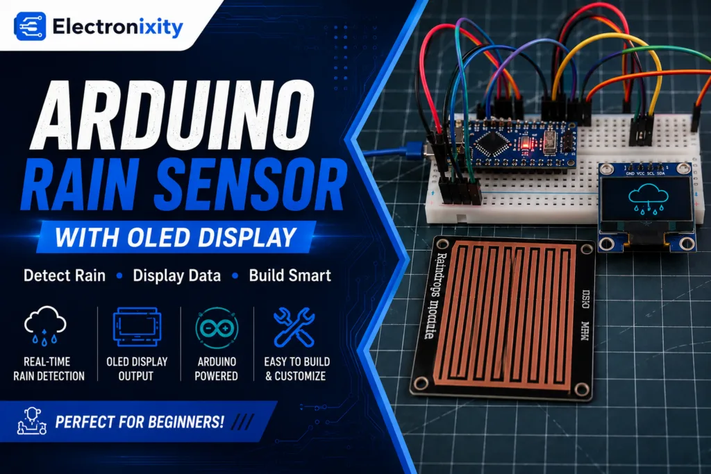
Fix: give the motor or strip its own supply and only share ground. This is the same failure mode that freezes OLEDs in servo projects — see the rain sensing wiper build, where an SG90 does exactly this to an Arduino Nano.
4. Powering 3.3 V directly, bypassing the regulator
Feeding the 3V3 pin from a bench supply or a battery through a weak regulator removes the board's own bulk capacitance from the path. The chip is then exposed to every dip the source makes.
Fix: feed 5 V into VIN and let the board's regulator do its job, or make sure your 3.3 V source is genuinely rated for the burst current and has bulk capacitance close to the pin.
5. Not enough decoupling
Long dupont leads plus no bulk capacitor near the board is a recipe for dips that a multimeter will never show you.
Fix: put a 100–470 µF electrolytic across the board's 5 V and GND, physically close to the board, with a 0.1 µF ceramic alongside it.
Do not "fix" this by disabling the brownout detector. Turning it off does not add a single millivolt to the rail — it just removes the warning, and the chip carries on executing at a voltage where flash writes are unreliable. A build that silently corrupts NVS is far harder to debug than one that reboots loudly.
How to confirm it before you buy anything
If you have a multimeter, measure the 3V3 pin while the fault happens. A meter is slow, so a dip that reads even slightly low on the display is a much deeper dip in reality — seeing 3.1 V on a meter during transmit means the real trough is well below that.
If you have an oscilloscope, put it on 3V3 with the timebase around 1 ms/div and watch for the step at the moment Wi-Fi connects. That single trace usually ends the argument.
A cheap software check: comment out the Wi-Fi connection and let the board run everything else. If the resets stop, the radio's current burst is the trigger, and you are looking at a supply problem rather than a code problem.
The parts that usually fix it
What you'll need
Live prices and stock from our catalog — add the lot in one tap.
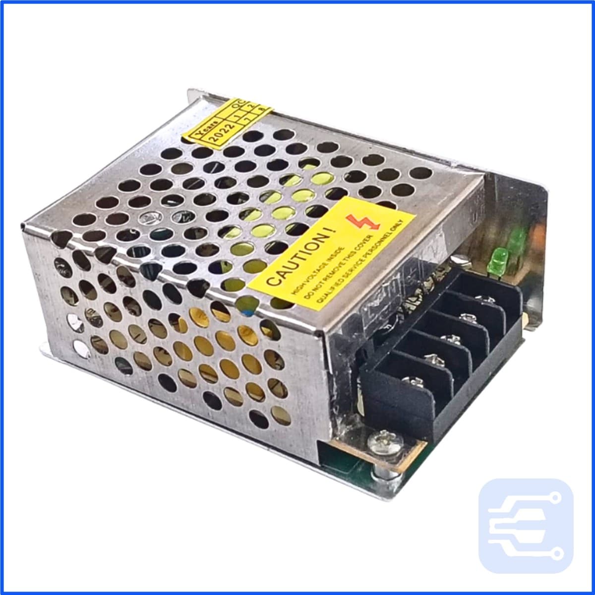
- 1×5V 2A SMPS Power SupplyA supply that can hold 5 V at 2 A under a load step, not just at idle.₹373In stock
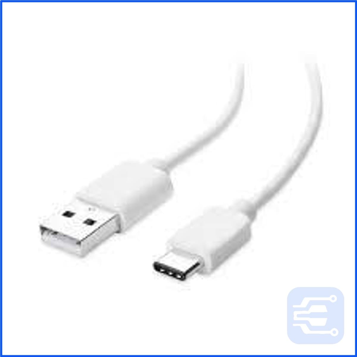
- 1×USB-A to USB-C Cable 1 MetreThin charge-only cables are a common hidden cause — the drop is in the cable.₹72In stock
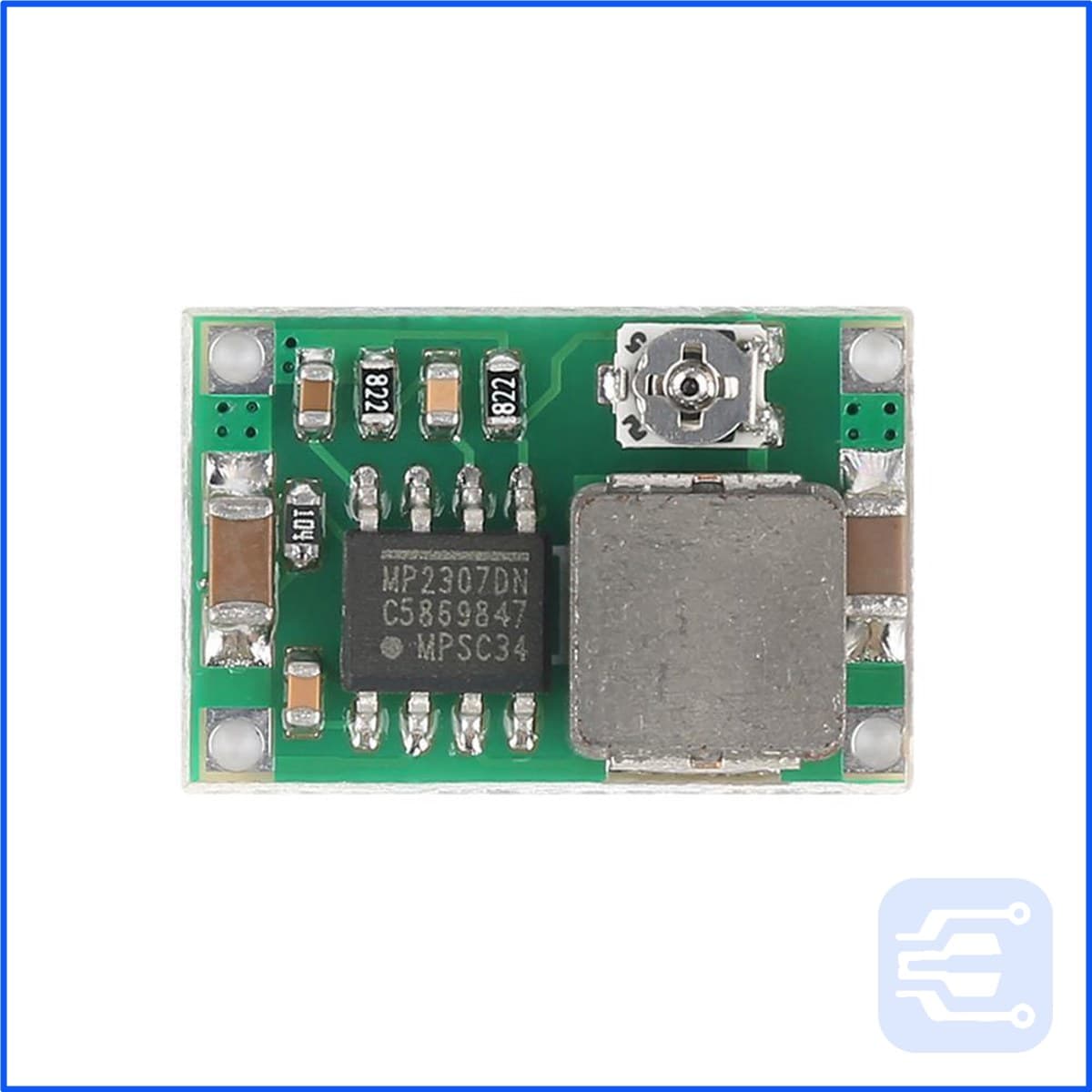
- 1×LM2596 Mini 360 DC-DC Buck Converter Step-Down ModuleFor feeding 3.3 V or 5 V from a battery pack instead of the USB rail.₹40In stock
Related failure modes
rst:0x8 (TG1WDT_SYS_RESET)is a watchdog reset, not a brownout — that one is usually a blocking loop in your code, not the supply.- Random resets with no brownout message point more often at a stack overflow or a null dereference than at power.
- Boot loops that mention
flash read errare a flash or strapping-pin problem; check that nothing is holding GPIO0, GPIO2 or GPIO12 at boot.
Frequently asked questions
Can I just disable the brownout detector?
You can, with WRITE_PERI_REG(RTC_CNTL_BROWN_OUT_REG, 0), and you almost certainly should not. The detector is not the fault — it is the only thing telling you the supply is collapsing. Disabling it converts a clean reboot into corrupted flash writes and readings that are silently wrong.
Why does it only happen when Wi-Fi connects?
Transmitting is the biggest current step an ESP32 makes — the radio can pull several hundred milliamps in bursts. A supply that looks fine at idle collapses on the first transmit, which is why the reset almost always lands at the moment of connection.
My board works on a laptop USB port but not on a phone charger. Why?
Many chargers need the data lines configured before delivering full current, and some cheap ones hold 5 V poorly under a fast load step. Try a different supply and a thicker cable before suspecting the board.
Is a brownout a sign my ESP32 is damaged?
Rarely. It is a supply symptom, not a board fault. Work through the supply, cable and decoupling first; a board that brownouts on one supply and runs perfectly on another is not the problem.